This short tutorial explains how to create new profile and how scripting engine works.
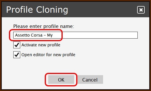
 3. Enter name for new profile and click OK.
 4. The Profile Editor will be opened.
5. For purpose of this exercise, remove all scripts except the one for Any platform.
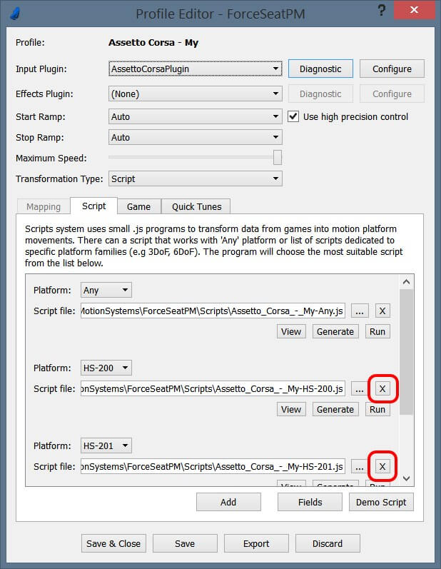 6. Click Save to apply changes.
7. Click View – it will open a directory contains the script.
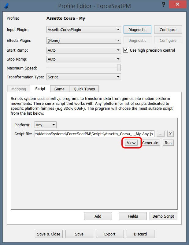 8. Finally open the script (*.js) in text editor (e.g. Notepad, Notepad++).
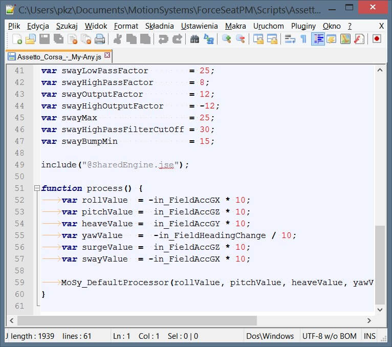 NOTE: ForceSeatPM monitors for changes in script file. It means that when the script file is modified in e.g Notepad, there is no need to reactive the profile. ForceSeatPM will automatically reload the script as long as the profile the script belongs to is still active.
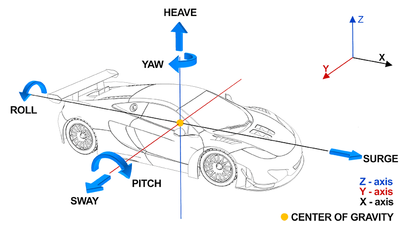 For both motion cueing mechanisms, it is very important to understand the relation between output values (axis values) and the actual platform motion:
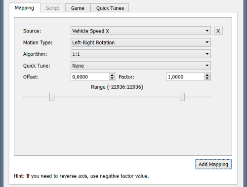
 Next step is mapping definition. Click Add Mapping and first item will be added to a list. There are following fields that need configuration:
 The final equation for single axis looks as follows:

 You can use the same source a few times and you can also use the same axis a few times. In this case final value for axis is just a sum.
In theory data mapping looks simple, but the trick is to find the best parameters values and the best combination of different source signals. Usually it takes hours of experiments and diagnostic module can be useful here.
Typical scenario looks as follows:
Creating new profile
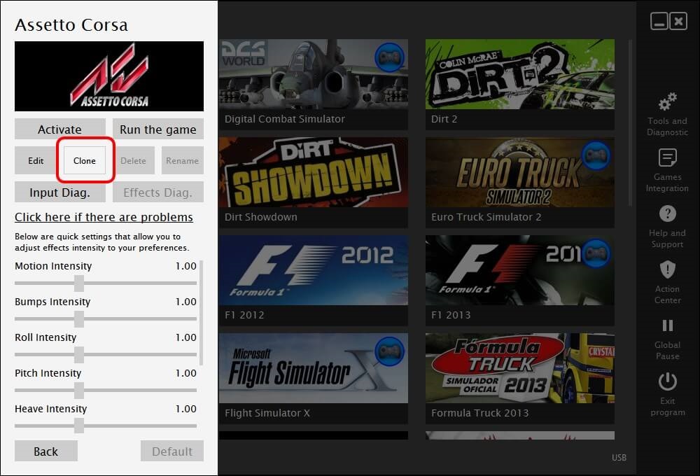
For most of supported games there are already built-in profiles. However in case a custom profile is needed, one can start from cloning existing profile or start from scratch. 1. Open main program window and click on existing profile. 2. Click Clone


 8. Finally open the script (*.js) in text editor (e.g. Notepad, Notepad++).

Input plug
Input plug-in defines source of main telemetry data. Below is a list of plug-ins and their purposes. Please notice that this list can change in next version of the software.- FlighSimulator – dedicated for Microsoft Flight Simulator X
- GPBikes – dedicated for PiBoSo GP-Bikes
- IL2 – dedicated for IL2
- Outsim – dedicated for games that uses Outsim protocol, for example: Live For Speed, GRID, GRID 2, Dirt, Dirt 2, Dirt 3, F1 2010, F1 2011, F1 2012
- RFBaseGame – for games that uses the same plug-in API as rFactor 1/ 2 e.g.: rFactor, rFactor 2, Game Stock Car 2012. Please notice that there is different connector for rFactor 2 comparing to rFactor 1 but still both are supported by the same plug-in on ForceSeatPM side.
- SimBinRace – dedicated for games from SimBin, e.g.: GTR2, Race 07 family, RaceRoom Racing Experience
- XPlane – dedicated for X-Plane 10, both x86 and x64
- DirectInput – it captures a steering wheel/joystick device, it can be used with any game that uses Microsoft DirectInput interface to interact with a game controller. Usually it is good to combine it with ForceFeedback as effect plug-in.
- ForceSeatMI – for programs and games that use MotionSystem ForceSeatMI API which is a part of ForceSeat SDK.
Motion cueing
Motion system moves according to the parameters specified in the motion profile. Input parameters come from input plug-in and/or effect plug-in and they can have different names depending on selected plug-ins. The final position of a platform is a result of combination and transformation of different values received from the game. This transformation can be performed by a mapping mechanism or by a script mechanism. The first one calculates final position of the platform by applying list of defined transformations of input values. It is easy in use but it is limited to predefined algorithms and transformations. The second one uses Javascript custom code that gets values from the game as input and outputs desired platform position. Please notice that instead of direct actuator positions, it is recommended to use axes. In this approach e.g. left-right rotation can be transformed by firmware into motion of two actuators for 2-dof platform but also for six actuators movement for 6-dof platform. It makes the profile more independent to the platform configuration. Following axes are used by ForceSeatPM and the platform firmware:- Left-Right rotation (Roll)
- Rear-Front rotation (Pitch)
- Horizontal Left-Right rotation (Yaw)
- Down-Up movement (Heave)
- Left-Right movement (Surge)
- Rear-Front movement (Sway)

- If you want to stop the platform in a center position all parameters should be equal 0.
- Maximum movement in each axis is represented by value of 32767 or -32767, for instance for left-right rotation, -32767 means maximum to the left, 32767 means maximum to the right
Data mapping transformation
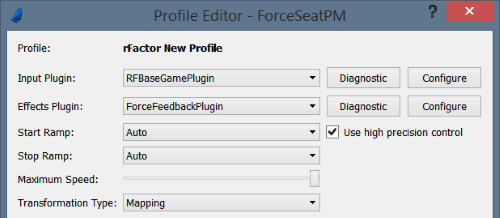
After selecting input and effects plug-in, it is time to define mapping between telemetry received from the game and platform movements. Let’s start with defining generic parameters:- Start Ramp – defines how fast an actuator should accelerate: rapid means that actuator will accelerate as fast as possible; very slow means that it can take even few seconds to achieve desired speed. Slow acceleration is recommended for flight simulators.
- Stop Ramp – similar as above, but for breaking/stopping.
- Maximum speed – maximum allowed actuators speed, the actuators will never move faster than this defined value. Please notice that setting this value to low can make the actuator not move at all.
- Transformation type – defines if mapping or script code is used during calculation of platform position, for this example mapping is selected.

- Source – name of the input value received from the game, usually it is good to use values related to acceleration in a vehicle coordinate system (e.g. Acceleration body X for rFactor)
- Motion type – name of a platform axis
- Algorithm– defines how to process telemetry value before sending it to the motion system:
- 1:1 – no processing, pass unchanged value.
- Delta Value – motion system receives the difference between a current value and a previous value.
- Average of Last 2, 3 or 5 – motion system receives an average value of recent N values.
- Offset – defines a contant value that is added to the parameter before it is proceeded.
- Factor – value from the game is multiplied by the factor after applying algorithm and offset.
- Range – the final value is reduced to defined range.


- Create a basic profile for the game.
- Activate the profile and open diagnostic for input/effects plug-in. It can be done from Profile Editor (by clicking Diagnostic button) or from a main program window in profile details view.
- Start the game in a windowed mode (if it is possible), otherwise use second display.
- Play the game and observe platform movements and also values in diagnostic window.
- Adjust the profile.
- Repeat steps 4 and 5 until results are as expected.
